- Getting Started
- Hardware
- Bricks
- Bricklets
- Master Extensions
- Power Supplies
- Discontinued Products
- Bricks
- Bricklets
- Accelerometer Bricklet
- Ambient Light Bricklet
- Ambient Light Bricklet 2.0
- Analog In Bricklet
- Analog In Bricklet 2.0
- Analog Out Bricklet
- CO2 Bricklet
- Current12 Bricklet
- Current25 Bricklet
- Distance US Bricklet
- Dual Button Bricklet
- Dual Relay Bricklet
- GPS Bricklet
- Humidity Bricklet
- Industrial Analog Out Bricklet
- Industrial Digital In 4 Bricklet
- Industrial Dual Analog In Bricklet
- Industrial Quad Relay Bricklet
- IO-4 Bricklet
- Laser Range Finder Bricklet
- LCD 16x2 Bricklet
- LED Strip Bricklet
- Load Cell Bricklet
- Moisture Bricklet
- Motion Detector Bricklet
- NFC/RFID Bricklet
- OLED 128x64 Bricklet
- Piezo Buzzer Bricklet
- PTC Bricklet
- PTC Bricklet 2.0
- Remote Switch Bricklet
- RGB LED Bricklet
- RGB LED Matrix Bricklet
- Rotary Encoder Bricklet
- Solid State Relay Bricklet
- Temperature IR Bricklet
- Thermocouple Bricklet
- UV Light Bricklet
- Voltage Bricklet
- Voltage/Current Bricklet
- Master Extensions
- Timeline
- Software
- Kits
- Embedded Boards
- Specifications
LED Strip Bricklet

Note
The LED Strip Bricklet is discontinued and is no longer sold. The LED Strip Bricklet 2.0 is the recommended replacement.
Features
- Controls up to 320 RGB or 240 RGBW LEDs
- All LEDs can be switched independently
- Update rate of up to 100Hz for each LED possible
Description
The LED Strip Bricklet can be used to control LED strips and LED pixels that are equipped with the WS2801, WS2811, WS2812/SK6812 (NeoPixel RGB), SK6812RGBW (NeoPixel RGBW), LPD8806 or APA102 (DotStar) LED driver. It is possible to independently control 320 RGB or 240 RGBW LEDs (960 individual LEDs) over the connected Brick.
The API allows to change all LEDs at the same time with a fixed update rate of up to 100Hz. A possible application can be found in the Starter Kit: Blinken Lights: Video
Brick Daemon 2.0.10 or newer is recommended for this Bricklet.
Technical Specifications
| Property | Value |
|---|---|
| Supported LED Drivers | WS2801, WS2811, WS2812/SK6812 (NeoPixel RGB),
SK6812RGBW (NeoPixel RGBW), LPD8806 and APA102 (DotStar)
|
| Current Consumption | 1mA (idle), 4mA (active) |
| Resolution | 8bit per LED |
| Maximum Number of LEDs | 960 (320 RGB or 240 RGBW LEDs)* |
| Maximum Update Rate | 100 updates per second |
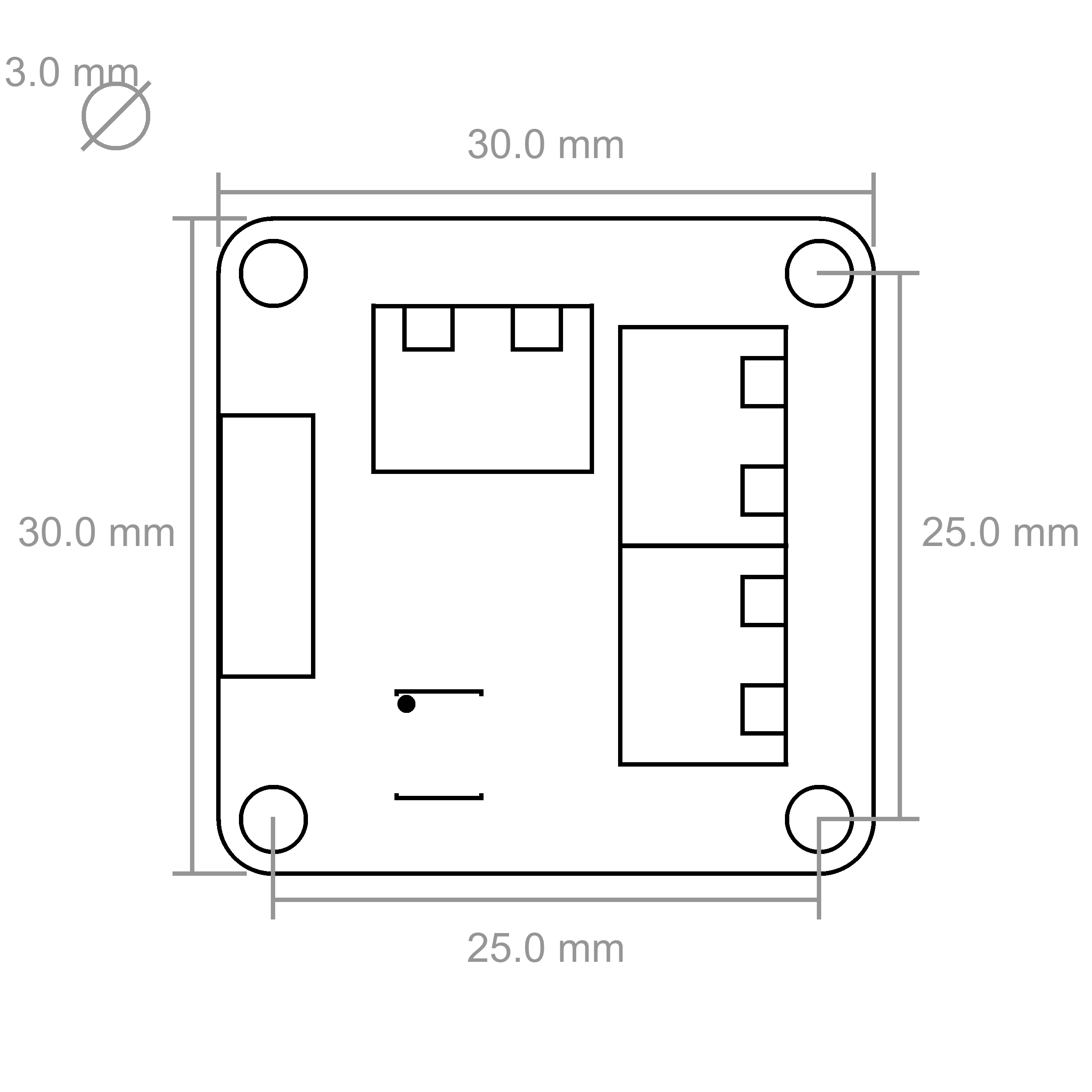
| Dimensions (W x D x H) | 30 x 30 x 12mm (1.18 x 1.18 x 0.47") |
| Weight | 10g |
* with a Master Brick, 480 with other Bricks
Resources
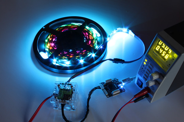
Test your LED Strip Bricklet
To test a LED Strip Bricklet you need to have Brick Daemon and Brick Viewer installed. Brick Daemon acts as a proxy between the USB interface of the Bricks and the API bindings. Brick Viewer connects to Brick Daemon. It helps to figure out basic information about the connected Bricks and Bricklets and allows to test them.
Connect the LED Strip Bricklet to a Brick with a Bricklet Cable. After that connect a LED strip or bunch of pixels to the Bricklet as described below.
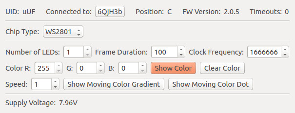
If you connect the Brick to the PC over USB, you should see a new tab named "LED Strip Bricklet" in the Brick Viewer after a moment. Select this tab. If everything went as expected you can now control a LED strip.
After this test you can go on with writing your own application. See the Programming Interface section for the API of the LED Strip Bricklet and examples in different programming languages.
WS2801, WS2811 and WS2812
The LED Strip Bricklet supports LED strips and pixels equipped with the WS2801, WS2811 or WS2812 driver chip. WS28xy refers to any of these chips.
You have to configure which of this driver chips you want to use with the
Brick Viewer or the set_chip_type() function of the LED Strip Bricklet.
WS2811 and WS2812 requires LED Strip Bricklet plugin version 2.0.2 or newer.
The WS28xy chips can control three LEDs independently. Typically a RGB LED combined in one package is used. It is controlled over a three or two wire chained data bus with clock (WS2801 only), data signal and ground as voltage reference (daisy chain). Each WS28xy chip has a bus input connected to a controlling device such as the LED Strip Bricklet or to a WS28xy predecessor and a bus output which can be connected to a subsequent WS28xy chip. Since it is a chained bus, a single bus output has to be connected only to a single bus input. The bus is indexed beginning with the first WS28xy on the LED Strip Bricklet (API index 0).
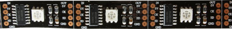
The above picture depicts a typical WS2801 LED strip. You can see each module equipped with one WS2801 chip and a connected RGB LED. Recognize the signal labels for input (IN) and output (OUT): 5V, CK (clock), SD (serial data) and GND. In contrast to the WS2801, the WS2811 and WS2812 driver chips don't have a clock signal.
Connectivity
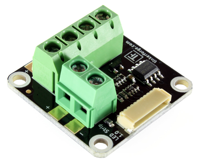
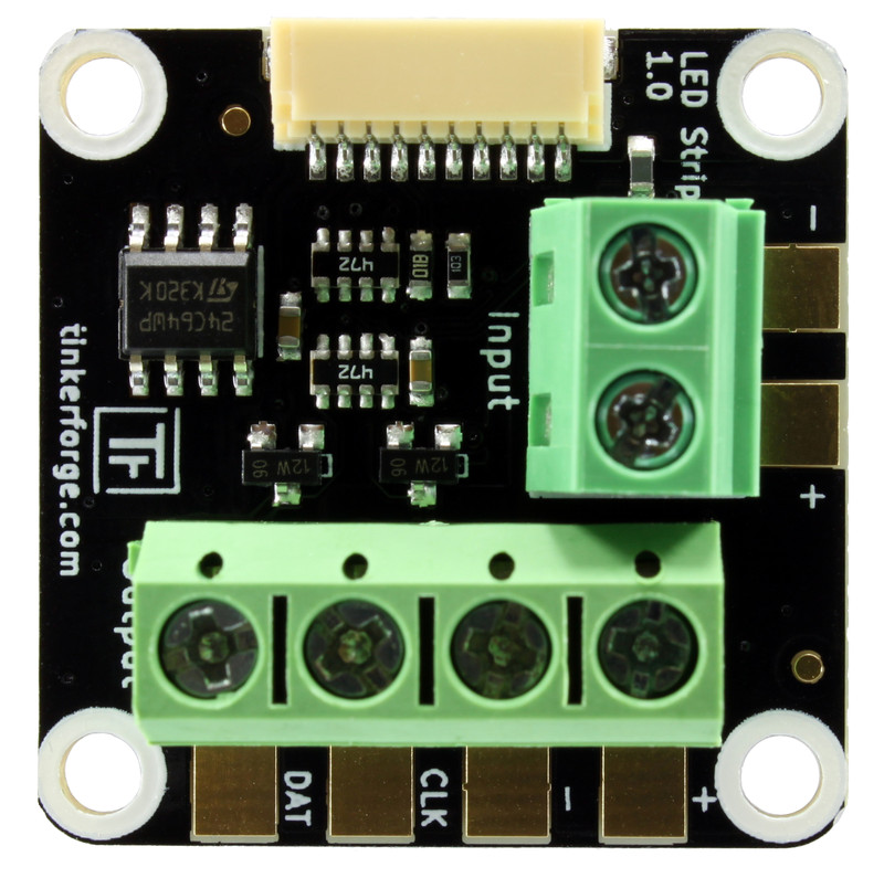
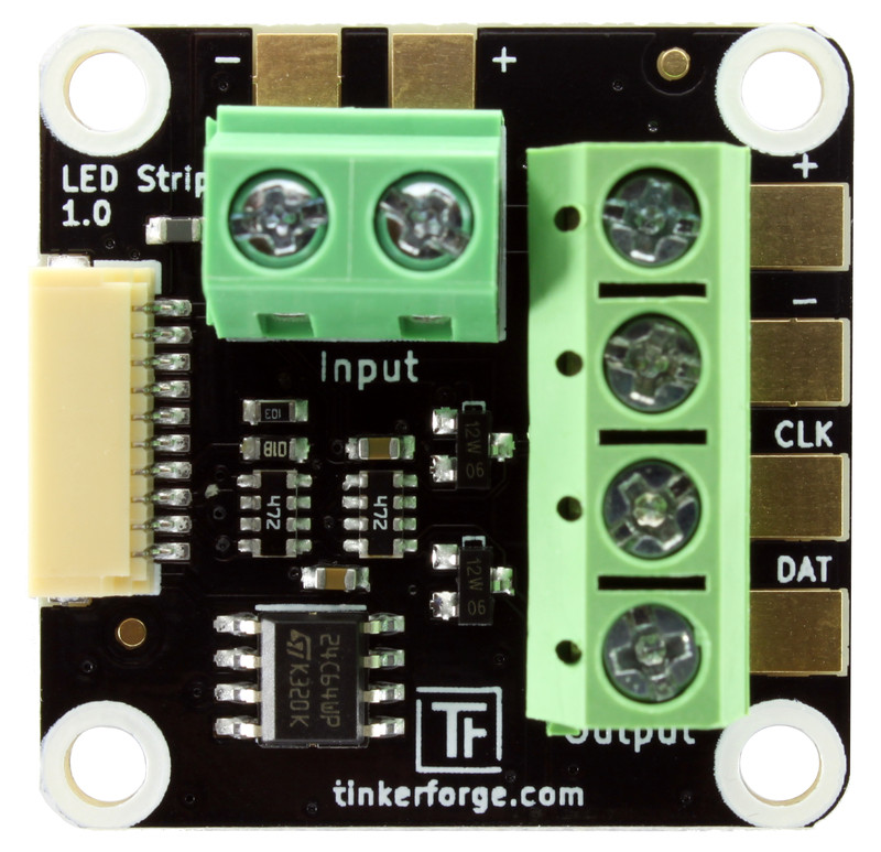
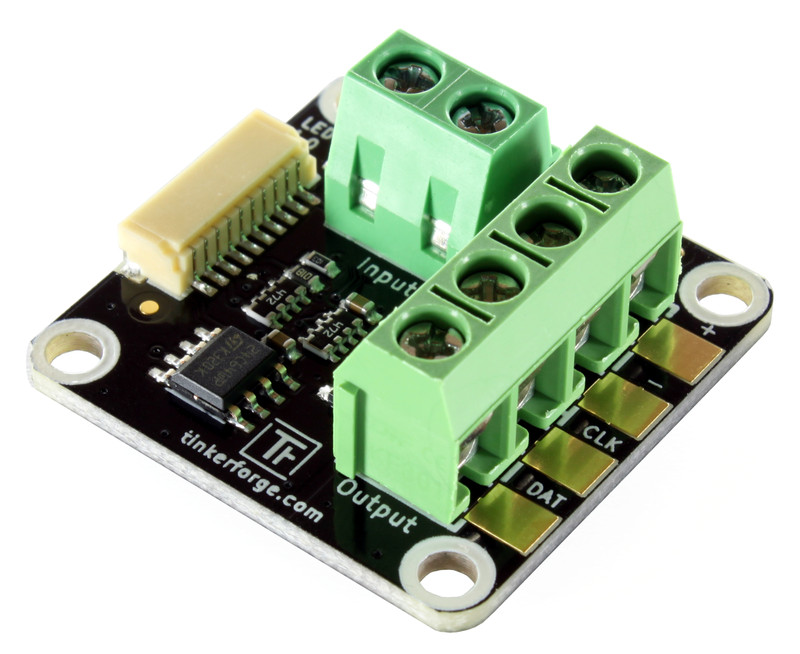
The following image depicts the interfaces of the LED Strip Bricklet.
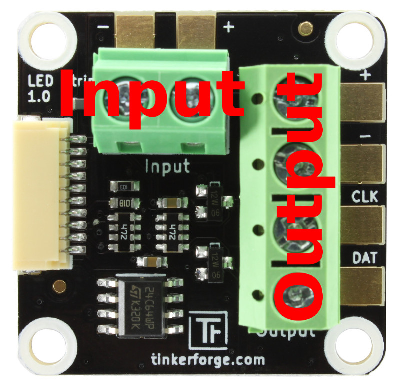
As described in the WS28xy section above, the Bricklet supports LED strips and pixels with WS2801, WS2811 or WS2812 driver. The terminal labeled with "Output" has to be connected with the input of the first WS28xy driver.
The output terminal consists of four signals:
"DAT" is the data signal line to the WS28xy chip. It has to be connected to the data input of the first WS28xy chip. Unfortunately there is no general label on LED pixels or on LED strips for this input. Sometimes the signal is marked with SD (Serial Data) or DI (Data Input). It is also possible that the input of the pixel or strip is not marked, but the output is marked (DO, Data Output). If the output is marked, the non marked other side has to be the input.
"CLK" is the clock signal line to the WS2801 chip. It has to be connected with the clock input of the first WS2801 chip. This input is typically labeled with CLK, CK or CI (Clock Input). If only the output is labeled it can be labeled with CO (Clock Output).
The WS2811 and WS2812 chips don't have a clock signal, leave the "CLK" terminal unconnected form them.
"-" is the ground signal line. Ground is necessary to give a reference for the DAT and CLK signals.
"+" is the supply voltage output. It is connected to the "+" signal of the "Input" terminal and should not be used to power LED Strips or pixels. Leave it unconnected and power the connected strip or pixels directly from your supply.
The input terminal consisting of two signals:
- "+" voltage supply input. It can be connected to the power supply for the LEDs to measure the supplied voltage. If you don't need this feature you can leave it unconnected.
- "-" is the ground input. It is internally connected with the "-" ground of the "OUTPUT" terminal.
RAM Constraints
The LED Strip Bricklet needs lots of RAM to store the color data for the LEDs. Normally the LED Strip Bricklet would only be able to control up to 80 RGB or 60 RGBW LEDs with the RAM that is available per Bricklet.
To circumvent this limitation, the LED Strip Bricklet is able to use the RAM of the remaining unconnected Bricklets. This allows to control up to 320 RGB or 240 RGBW LEDs with one Master Brick and one LED Strip Bricklet. As described above these used ports can't be used by other Bricklets.
The maximum number of controllable LEDs is as follows:
| Free Bricklet Ports | Maximum number of RGB LEDs | Maximum number of RGBW LEDs |
|---|---|---|
| 0 | 80 | 60 |
| 1 | 160 | 120 |
| 2 | 240 | 180 |
| 3 | 320 | 240 |
WS2812B LED Strips
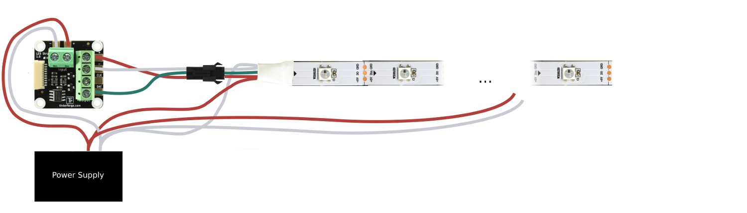
There is no general color code for LED strips. Especially sometimes the color codes are against any agreements. In this WS2812B LED strip example the red wire is 5V, green is data the white wire is ground.
Connect data of the first strip to the LED Strip Bricklet and connect ground of your power supply to it. Pay attention to connect the data input of the first strip to the data output of the LED Strip Bricklet.
If you want to measure your supply voltage connect 5V to the Bricklet, too. You can connect more LED strips to the first strip in series (have the RAM constraints in mind).
It is not sufficient to power the LED strips only at one point. We recommend to feed power to the strip at least every two meters. This can be done by connecting a cable between the strip and the power supply for each supply point. This will reduce the resistance and minimize the conduction losses. See the following image as an example for it.
WS2801 LED Strips
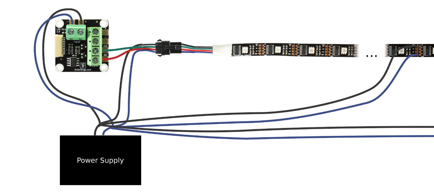
There is no general color code for LED strips. Especially sometimes the color codes are against any agreements. In this WS2801 LED strip example the black wire is 5V, green is clock, red is data and the blue wire is ground.
Connect clock and data of the first strip to the LED Strip Bricklet and connect ground of your power supply to it. Pay attention to connect the clock and data input of the first strip to the clock and data output of the LED Strip Bricklet.
If you want to measure your supply voltage connect 5V to the Bricklet, too. You can connect more LED strips to the first strip in series (have the RAM constraints in mind).
It is not sufficient to power the LED strips only at one point. We recommend to feed power to the strip at least every two meters. This can be done by connecting a cable between the strip and the power supply for each supply point. This will reduce the resistance and minimize the conduction losses. See the following image as an example for it.
LED Pixels
The connection of LED pixels to the LED Strip Bricklet is similar to the connection of LED strips. There is no general color code for LED pixels. In the following example the red wire is 5V, blue is ground, clock (WS2801 only) is green and data is the white wire.
Connect clock (WS2801 only) and data of the first bunch of pixels to the LED Strip Bricklet and connect ground to it. Pay attention to connect the clock (WS2801 only) and data input of the first pixel to the clock (WS2801 only) and data output of the LED Strip Bricklet. If you want to measure the voltage of your power supply connect 5V to the Bricklet, too. You can connect more bunches of LED pixel to the first bunch in series (have the RAM constraints in mind).
Typically each bunch has power supply wires at the beginning and the end of the bunch. Connect these over additional wires to the power supply. You can unite nearby wires. This will reduce the resistance and minimize the conduction losses.
Fixed Frame Rate
To achieve a smooth animation a fixed frame rate is desirable. A fixed frame
rate is easy to achieve with a properly configured frame duration and the
FrameRendered callback. The frame duration configures the amount of time
between each frame in ms. The FrameRendered callback is triggered after
a frame is transfered to the LEDs.
For example, if you want to have an animation with 20 frames per second, you
should set the frame duration to 50ms. After the frame duration is set you
need to send the first frame (i.e. you need to set all RGB values), wait
until the FrameRendered callback is triggered, write the next frame and so on.
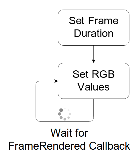
If you receive a FrameRendered callback before all LEDs are set, your frame
rate is too high.
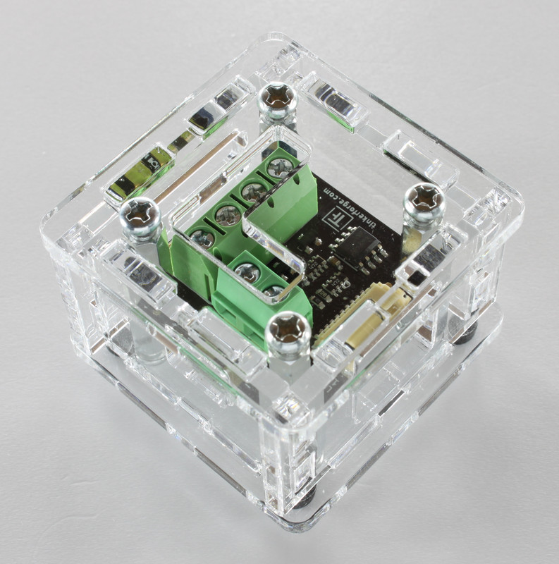
Case
A laser-cut case for the LED Strip Bricklet is available.

The assembly is easiest if you follow the following steps:
- Screw spacers to the Bricklet,
- screw bottom plate to bottom spacers,
- build up side plates,
- plug side plates into bottom plate and
- screw top plate to top spacers.
Below you can see an exploded assembly drawing of the LED Strip Bricklet case:
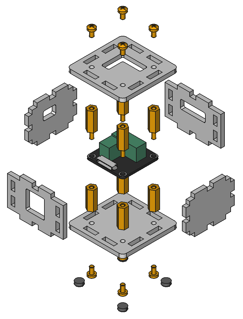
Hint: There is a protective film on both sides of the plates, you have to remove it before assembly.
Programming Interface
See Programming Interface for a detailed description.
| Language | API | Examples | Installation |
|---|---|---|---|
| C/C++ | API | Examples | Installation |
| C# | API | Examples | Installation |
| Delphi/Lazarus | API | Examples | Installation |
| Go | API | Examples | Installation |
| Java | API | Examples | Installation |
| JavaScript | API | Examples | Installation |
| LabVIEW | API | Examples | Installation |
| Mathematica | API | Examples | Installation |
| MATLAB/Octave | API | Examples | Installation |
| MQTT | API | Examples | Installation |
| openHAB | API | Examples | Installation |
| Perl | API | Examples | Installation |
| PHP | API | Examples | Installation |
| Python | API | Examples | Installation |
| Ruby | API | Examples | Installation |
| Rust | API | Examples | Installation |
| Shell | API | Examples | Installation |
| Visual Basic .NET | API | Examples | Installation |
| TCP/IP | API | ||
| Modbus | API |